All Activity
- Yesterday
-
GauyREele joined the community
-
Vidéo There's no payout. You'll see at the end, I reset the counter to zero, and the boss gives me 100-franc notes, representing my winnings. Just kidding. Give me the cash. And next customer... ------------------------------------------------------ Damn, the video won't play. Oops, the video won't play. It appears, but there's no sound. So: Here's a link to download the video. Or if someone could put it directly on the site. I'll remove the link then. ------------------------------------------------------ https://mega.nz/file/Ql9RESAA#2xp4A4V0Q-_Vl41q7oUYPKTJeAFH-Zwd7HRm0Q2NwrY
-
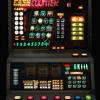
Hello I've prepared a video as promised. You'll notice some artistic blurring. It's a large file, 2GB. I don't know if it will be accepted on the site. Before, I've included two photos for the payout table. Note that the biggest win was 3000 + 1500 = 4500 francs. At the time, that was a nice sum. But, if I remember correctly, I never actually saw it. The biggest win I saw was 1500 francs. But let's be honest, the winner wasn't the player. It was the café owner and the machine operator. They made a small fortune during that period. How do I know? In my parents' brasserie, where I worked, there were 4 slot machines and 2 video poker machines. There you go; enjoy the video.
-

Artwork (polycarbonate and reel printing)
sulzerned replied to MattyL's topic in OLD FRUITY DISCUSSION
Ive emailed him -

Artwork (polycarbonate and reel printing)
netdent replied to MattyL's topic in OLD FRUITY DISCUSSION
fingers crossed he can sort this out -

Artwork (polycarbonate and reel printing)
sulzerned replied to MattyL's topic in OLD FRUITY DISCUSSION
That sounds perfect ronnie as I need a set of back lit stake up bands doing as well as front lit bands for older machines . -

Artwork (polycarbonate and reel printing)
netdent replied to MattyL's topic in OLD FRUITY DISCUSSION
midasororey@yahoo.es Really helpful guy and knows his onions on backlit stuff and printing once he uderstands what you need -

Artwork (polycarbonate and reel printing)
sulzerned replied to MattyL's topic in OLD FRUITY DISCUSSION
How do we get hold of him ronnie ? -

Artwork (polycarbonate and reel printing)
netdent replied to MattyL's topic in OLD FRUITY DISCUSSION
The guy that done my Big Shot glass may be able to do these Mikonos, and he was reasonable on cost for me -
fedexprinting joined the community
- Last week
-

Artwork (polycarbonate and reel printing)
sulzerned replied to MattyL's topic in OLD FRUITY DISCUSSION
Not totally sure but I think generally a high quality paper is used and then laminated .I know alan (road runner ) has drawn up bands in the past but he has then sent the file off to printers . He did one or two sets for me and what made the difference for.me was that we managed to get an off white light cream colour for the background band colour to give a slightly" used "look which was much better than just a pure white which looked too new . -
Yeah... is there any info on what type of material is used on reel bands? Some kind of styrene?
-
sulzerned started following Artwork (polycarbonate and reel printing)
-

Artwork (polycarbonate and reel printing)
sulzerned replied to MattyL's topic in OLD FRUITY DISCUSSION
Would love some bands doing for a couple of.my machines so if anyone contacts you on here or elsewhere I'd be interested. -
Luvslots joined the community
-
Hello everyone ! I'm fresh new in the fruit machine system. Hope to find help and good friends here
-
Zarbel joined the community
-
Hi folks, Ive got some rare game artwork id like to print out-we've also got a graphics designer at work that will help me out tidying up the artwork... does anyone know anything about the printing processes or what companies do it-especially reel bands? Ive seen many people look into it over the years but not many people see it through- which is mad because of how many machines and reels have been produced over the years... is it niche or what?
-
yes that looks fine, 47 ohms 3w resistor will be fine with a 16 ohm speaker 👍 as long as it is close or near enough i would say it's fin. good work!
-
Hello! Fantastic!! It's good practice for you and a real boost for me. I understand everything. (I think...) I've got my calculator out again. Ohm's law. Thanks! Soon, I'll replace the original 27-ohm resistor with a 47-ohm 4W one. That will bring the resistance down to 63 ohms. It'll be cleaner, too. Please don't hold it against me. I'm slow to react, and sometimes the translation isn't straightforward. But we'll get there, with the explanations from Bob, JimXXX, Andrew... Thanks!
-
Any chance of some hi res images of the machine in a off state need some of the whole machine in view some of the full top glass in view mans some of the whole bottom glass including buttons in view then this can finally be made into a dx (a real looking layout) thanks
-
I am having a Problem with error 16 keeps displaying; have taken out note exceptor but it still finds error 16; cleaned out coin storage and checked all that; all works fine; but when I startup does everything fine even with the note exceptor in; when I go with the dil switches right and left fo the exceptor to be enabled right hand dil switch number 8 on "error 16" with or without a note exceptor in (is The Pub Lanlord 2012 machine Pluto 6 Board ) what do you think, I am thinking board error I am just stuck at mo bill
-
Hi all. Hope everyone is good. I was a member here years ago before the covid days. I was fruitypie. I am now back and want to restart building a club machine collection if possible. I say this as I have noticed buying 80s 90s fruit machines have become very scarce. And what is out there to the public are very high prices. Anyone with a club machine who is selling please get in touch with me.
-
I don't think pushers can be emulated unfortunately. but i could be wrong though.
-
just done some working out, with the resistor 27 ohms and the speaker at 30 ohms this totals 57 ohms, the supply is 12v so when the transistor T11 turns on 210ma passes through the transistor collector to emitter, that's 2.53watts, the transistor is rated for 800ma. but if the 30 ohm speaker is replaced with 8 ohm this becomes 27ohm resistor +8 ohms = 35 ohms, so the current goes up to 343ma and 4.12 watts! its still well within the transistors switching capacity, but as its most likely 40 year old transistor it will most likely die as these are prone to failing with age even when everything is all correct! also the increased current and switching the transistor on and off rapidly to create the 'tone' will cause heat in the transistor junction which can also cause the transistor to fail, but may be fine for a while. so its up to you really what you do. Others will say just change the speaker from 30 ohms to 8 ohms, and yes it will work, but it is entirely up to you if you want to do that, or do it properly. I would presume 30 ohms was chosen so a 3w 27 ohm resistor would be well within the ratings, with the 8 ohm speaker 4.12w puts the 27 ohm resistor as well under rated at just 3w
-
👍👍 perfect
-
Hello. In this temporary setup, I now have 28 ohms. That will rest T11. Thanks, Andrew. I'll order the necessary parts with my next order. For the upcoming video, should I post it in this same thread or elsewhere? Thanks.
-
Not always the case! I sold an untested epoch mpu on ebay a few years back sold for 12 quid, the buyer messaged me to say it fully worked, I also have loads of parts that have never been tried, but yes mostly bought untested means gubbed, I would rather list it as known to be faulty
-
We’ve all said this before but ‘untested’ or ‘not working but may just need a fuse’ are always total bollocks. Both = fucked.


